
Static Test Stand
READ ME
Read the Read Me file before proceeding further.
Overview
- Members: Dhruv Kakade, Abhay Nandan U, Akshay M, Athrv Kadam, Chethan S
- Period: [October 2025]
Nomenclature
IMRC - IN-SPACe Model Rocketry Competition
Manufacturing and Assembly
Uses M5 Allen Bolts, t-nuts and clamps. The test stand consists of the following components.
Table 1: Bill of materials for test stand
| Component | Specification | Quantity |
|---|---|---|
| Extrusion Rods | 30x30mm, 300mm | 8 |
| Extrusion Rods | 30x30mm, 400mm | 5 |
| Extrusion Rods | 30x30mm, 1000mm | 4 |
| Screw Rods | M8, 500mm | 8 |
| 20x20 Clamps | - | 28 |
| Allen Bolts and t-nuts | M5 | 58 |
| Loadcell | 1T Capacity | 1 |
| Load Cell Allen Bolts and Nuts | M12, 50mm | 2 |
| Espressif 32 | Node MCU, ESP32-S | 2 |
| Load Cell Amplifier Module | HX711 | 1 |
| Relay | 30V 10A | 1 |
| Tenka (点火) Assembly PCB Board* | As per doc SR004 | 1 |
Testing & Data
Setup
The setup consists of a frame made of aluminum extrusion with a height of 1000mm and 300mm sides. there are 8 screw rods to support the motor vertically on the setup and such that it can help the motor to advance downward towards the loadcell applying a load to get the thrust readings by loadcell . The following sections discuss about how the readings were taken and the safety precautions used and available at the site of testing.
Instrumentation
The Node MCU Espressif 32 board was used as a micro-controller to calculate the thrust measured.
Safety measures
A fire extinguisher and a bucket of water was near by such as to extinguish fire from any kind of a blast. The team for member maintained a distance of 75-100m away from the test stand and all the ignition was done wirelessly using the ESP-NOW protocol on Node MCU Espressif 32 boards as well as for transferring data. Through this setup. The setup can be done using a LoRa, XBee or similar radios that are capable of full duplex communication.
Results
The test for a J-Class SRM was performed successfully and the following information was obtained through the static fire test. For a detailed calculation of the result check the archive document on J Class SRM static fire test here.
Gallery
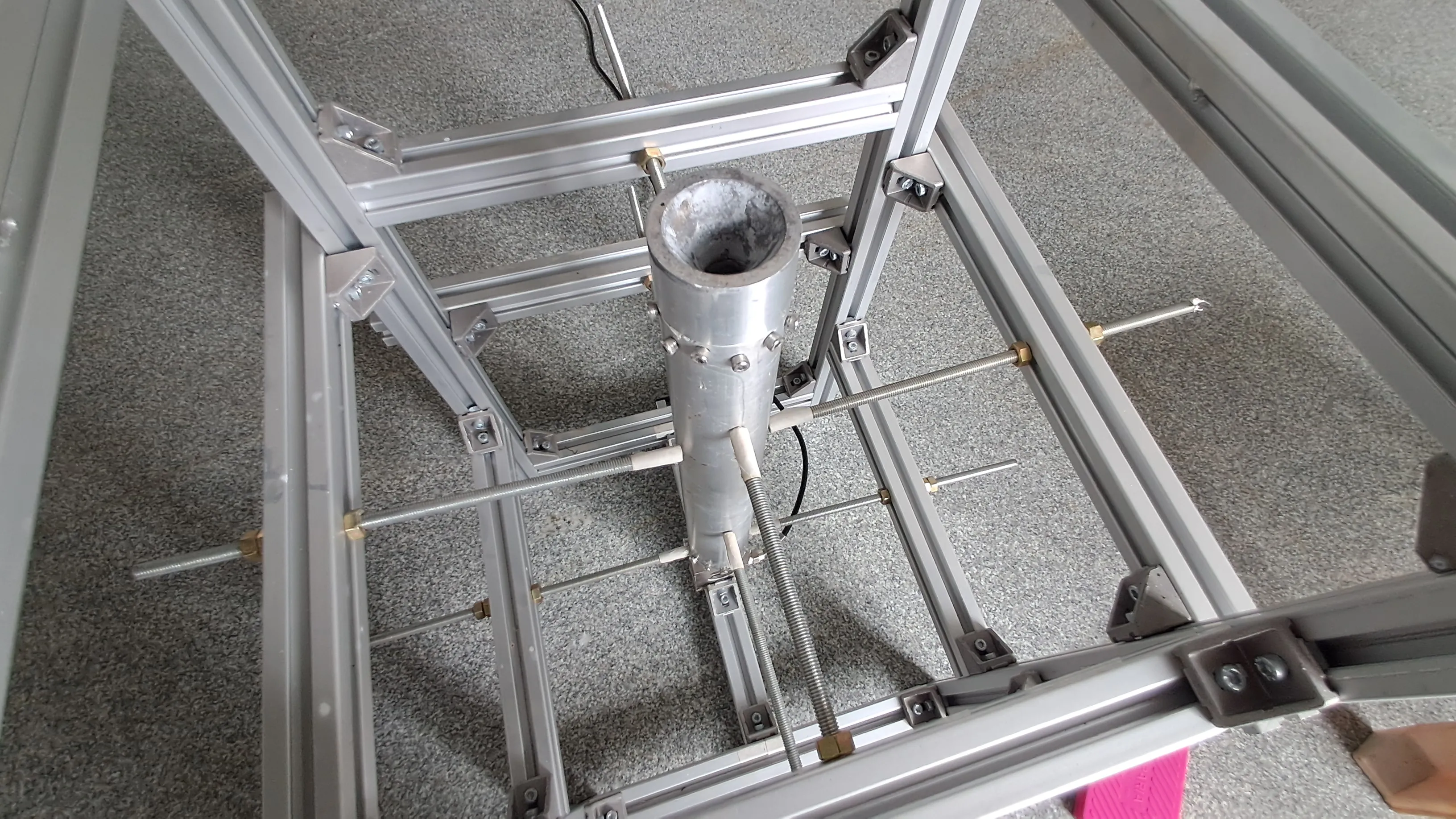
Figure 1: Test stand setup
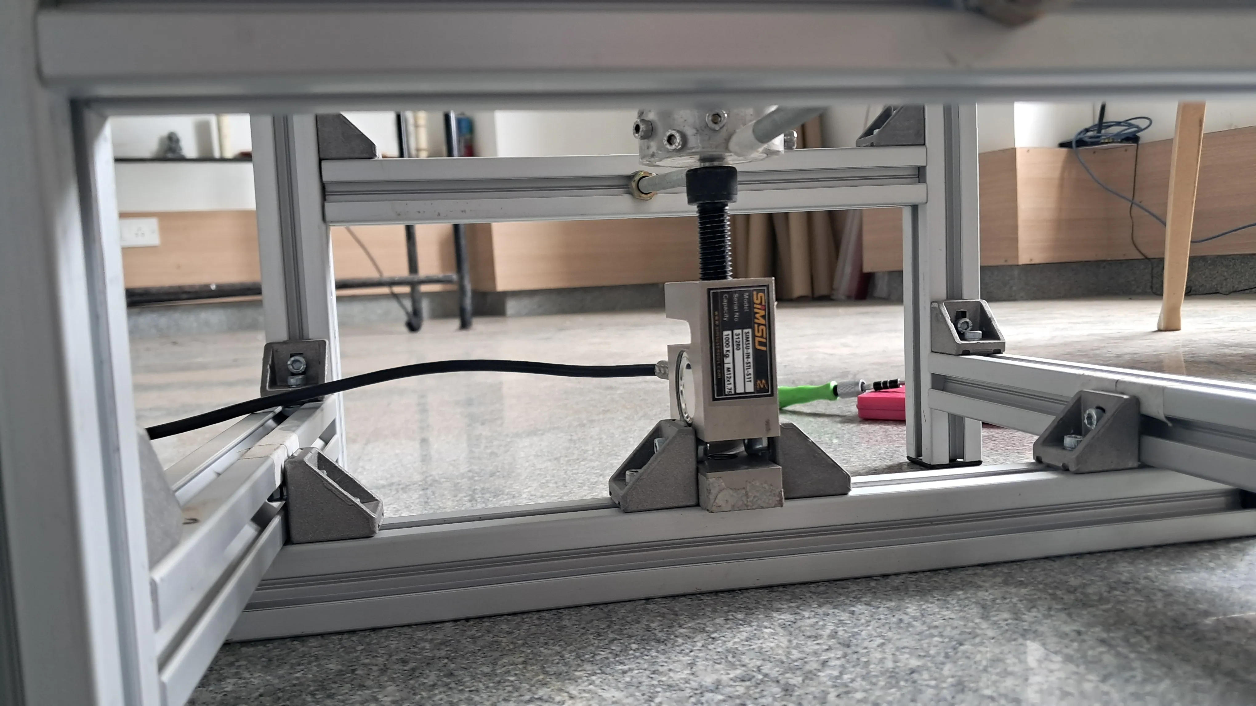
Figure 2: Loadcell placement
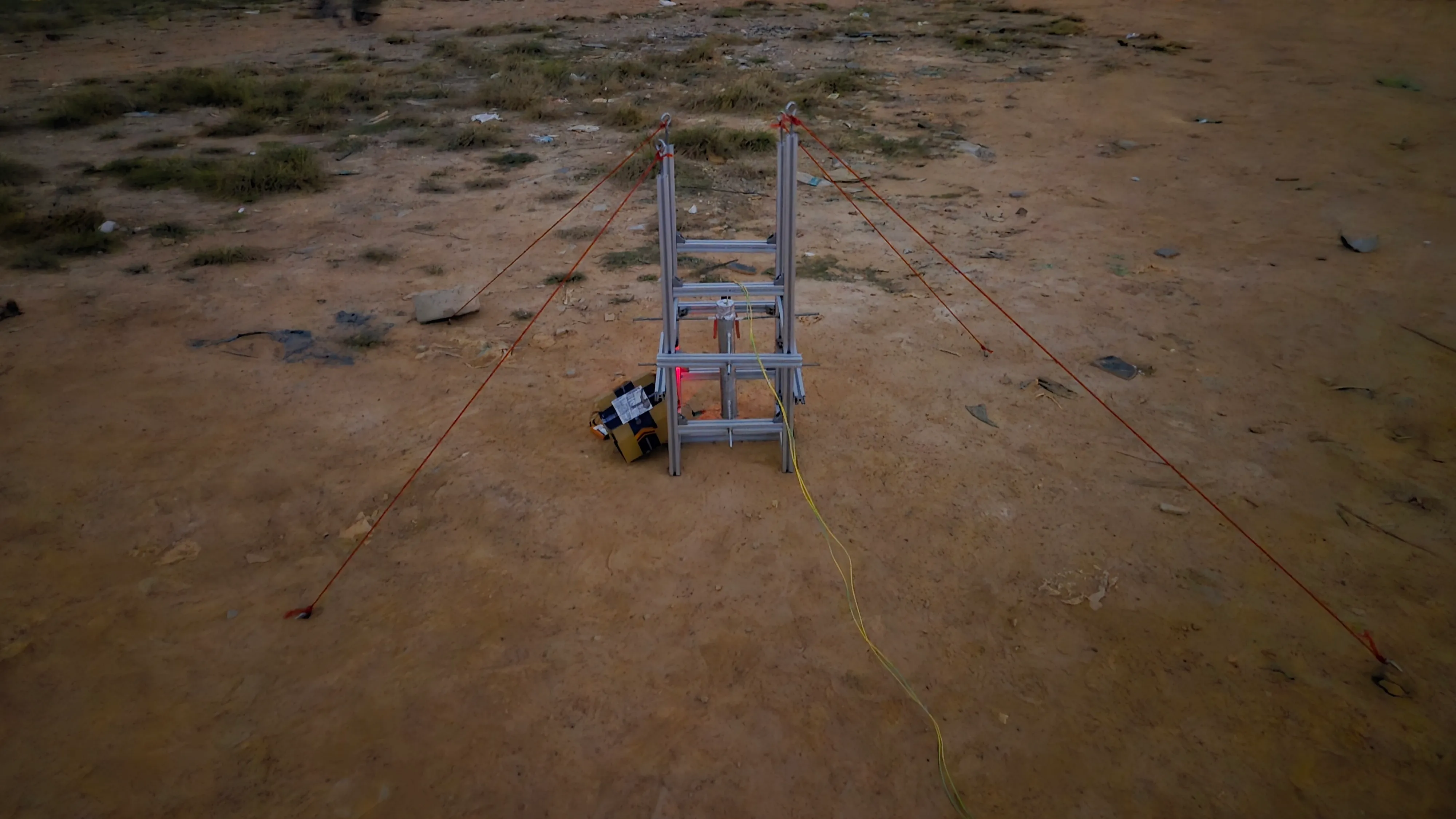
Figure 3: Harnessed test stand on ground
Video 1: Static fire of the J-class SRM
CAD Model Download
The can models are designed and avaliable for download through Onshape as well as Autodesk Fusion 360 and are avaliable at Onshape.
Code
Open-sourced after the IMRC2026 Competition (Refer document SR004-26).
Future Work
- Update to reuseable E-matches by using thicker nichrome wires.
- Use a better motor design and make a good machined retainer to hold all kinds of motors.
*to be open sourced after IMRC 2026
For any errors, mistakes or any issues contact: Dhruv Kakade (Co-Team Lead), dhruvkakade5@gmail.com